Ultrasonic Measurements
by Pamela Burnley, University of Nevada Las Vegas
Outline
Introduction
Techniques
Guest Lecturer
Literature
Problem Set
Related Links
Introduction
The sound wave velocity as a function of depth in the earth is one of the few things that we can directly measure about the earth's interior. Models for the composition of the earth's interior are developed and validated by comparing measured sound speeds of candidate earth materials at pressure and temperature with what we observe for the earth.
The simplest way to measure sound speed in the lab is to introduce a sound wave into a long span of a material and then to observe how long it takes for the sound wave to get to the other end. There are a number of reasons why this approach is less than optimal, including the difficulty of finding a pure, crack free block of the material that is large enough to produce a measurable travel time. A variety of other strategies have been tried, but the one that is best suited for high pressure work is ultrasonic interferometry.
Ultrasonic Interferometry
Ultrasonic work can be done on several scales depending on the sample size. In the multi-anvil samples are ~1 mm in length so an optimal wave length is in the Megahertz range. For diamond anvil cell samples which are on only ~100 microns in thickness Gigahertz frequencies are optimal
Ultrasonic interferometry in the Multi Anvil
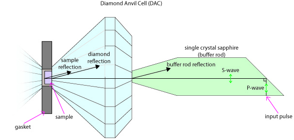
Ultrasonic interferometry in the Diamond Anvil Cell
Gigahertz ultrasonic interferometric experiments conducted in the DAC permit very tiny samples to be measured at pressures exceeding what can be achieved in the multianvil. A good place to learn about this technique is Steve Jacobson's web page

Guest Lecturer
"Ultrasonic Interferometry at High Pressures and Temperatures" Prof. Robert Liebermann
Part 1 (30 minutes) (MP4 Video 38.4MB Jul9 21)
Part 2 (25 minutes) (MP4 Video 33.7MB Jul9 21)
Part 3 (30 minutes) (MP4 Video 44.1MB Jul9 21)
Literature
Anderson, O.L., and Liebermann, R.C.. Sound Velocities in Rocks and Minerals: Experimental Methods, Extrapolations to Very High Pressures, and Results, in Physical Acoustics: Principles and Methods. Mason, W.P., ed. Academic Press, New York, 1968, p. 329-472.
Anderson, O.L., Schreiber, E., and Liebermann, R.C., (1968). Some Elastic Constant Data on Minerals Relevant to Geophysics, Reviews of Geophysics, 6(4), 491-524.
Jacobsen, S. D.; Spetzler, H. A.; Reichmann, H. J.; Smyth, J. R.; Mackwell, S. J.; Angel, R. J.; Bassett, W. A. (2002). Gigahertz ultrasonic interferometry at high P and T: new tools for obtaining a thermodynamic equation of state. Journal of Physics : Condensed Matter, 14, 11525-11530.
Li, B., and Liebermann, R.C., (2007). Indoor seismology by probing the Earth's interior by using sound velocity measurements at high pressures and temperatures, PNAS, 104(22), 9145-9150.
Li, B., J. Kung, and R.C. Liebermann, Modern techniques in measuring elasticity of Earth materials at high pressure and high temperature using ultrasonics in conjunction with synchrotron X-radiation, Phys. Earth Planet. Interiors, 143-144, 559-574, 2004.
Li, B., J. Kung, Y. Wang, and T. Uchida, Simultaneous equation of state, pressure calibration and sound velocity measurements to lower mantle pressures using multi-anvil apparatus, In: Frontiers in High Pressure Research: Geophysical Applications. Editors: J. Chen, Y. Wang, T. Duffy, G. Shen, L. Dobrzinetskaya, Elsevier, New York, pp.49-66, 2005.
Spetsler, H.A., Chen, G., Whitehead, S., and Getting, I.C. (1993). A new Ultrasonic Interferometer for the Determination of Equation of State Parameters of Sub-millimeter Single Crystals, PAGEOPH, 141 (2/3/4), 341-377.
Related Links
Steven Jacobsen at Northwestern
Acknowledgements
These materials are being developed with the support of COMPRES, the Consortium for Materials Properties Research in Earth Sciences, under NSF Cooperative Agreement EAR 10-43050 and is partially supported by UNLV's High Pressure Science and Engineering Center, a DOE NNSA Center of Excellence supported under DOE NNSA Cooperative Agreement No. DE FC52-06NA26274.


