Bragg's Law
Summary

![[creative commons]](/images/creativecommons_16.png)

"ON A COLD WINTER DAY IN DECEMBER, 1955, Robert Wentorf Jr. walked down to the local food co-op in Niskayuna, New York, and bought a jar of his favorite crunchy peanut butter. This was no ordinary shopping trip, for Wentorf was about to perform an experiment of unsurpassed flamboyance and good humor. Back at his nearby General Electric lab he scooped out a spoonful, subjected it to crushing pressures and searing heat, and accomplished the ultimate culinarytour de force: he transformed peanut butter into tiny crystals of diamond."
- from The Diamond Makers by Robert M. Hazen (1999), Cambridge University Press
So, how can we determine whether an experiment designed to produce diamonds has actually delivered the intended result? One diagnostic test we can perform is X-ray diffraction, a technique that depends upon Bragg's Law.
This activity is designed to facilitate an understanding of Bragg's Law and how it applies to X-ray diffraction techniques used in the performance of high pressure research at beamlines, such as X17B2 at the National Synchrotron Light Source at Brookhaven National Laboratory.
Context
Audience
Skills and concepts that students must have mastered
How the activity is situated in the course
Goals
Content/concepts goals for this activity
Students will learn:
- Where Brookhaven National Laboratory is located (via Google Earth) and what it is.
- Where the National Synchrotron Light Source is located (via Google Earth).
- What the National Synchrotron Light Source is.
- What a beamline is.
- D-spacings in crystal lattices.
- Bragg's Law and X-ray diffraction.
- How we can use X-ray diffraction to distinguish between diamond and graphite.
Higher order thinking skills goals for this activity
spatial visualization of electromagnetic wave phenomena
analysis of data
evaluating hypotheses
Other skills goals for this activity
d-spacing
X-ray diffraction
high-pressure analysis techniques
Description of the activity/assignment
It may be beneficial to have students perform the Wave Interference activity prior to engaging them in this activity.
The following handouts are identical, with the exception that one is in Word format, while the other is in PDF format. The students should perform the exercise in a computer laboratory. Before proceeding through the questions, they should be given an opportunity to review the material on this web page.
Bragg\'s Law Activity Sheet (Acrobat (PDF) 73kB Mar2 10)
Bragg\'s Law Activity Sheet for Word (Microsoft Word 37kB Feb25 10)
The following Powerpoint presentation can be used as an introduction to Bragg's Law.
Bragg\'s Law Powerpoint Presentation (PowerPoint 974kB Feb25 10)
Wave Interference Activity
Prior to investigating Bragg's law through this activity, it may be helpful to explore interference of sinusoidal waveforms by following the link below.
Bragg's Law Applet
Java Applet created by Konstantin Lukin with supervision by Glenn A. Richard, Project Java WebmasterOriginal Bragg's Law Applet page on Mineral Physics Institute web server at Stony Brook University:
Project Java - Bragg's Law and Diffraction: How waves reveal the atomic structure of crystals
Bragg's Law refers to the simple equation:
nλ = 2d sinΘ
derived by the English physicists Sir W.H. Bragg and his son Sir W.L. Bragg in 1913 to explain why the cleavage faces of crystals appear to reflect X-ray beams at certain angles of incidence (Θ, λ). The variable d is the distance between atomic layers in a crystal, and the variable lambda is the wavelength of the incident X-ray beam (see applet); n is an integer.
This observation is an example of X-ray wave interference (Roentgenstrahlinterferenzen), commonly known as X-ray diffraction (XRD), and was direct evidence for the periodic atomic structure of crystals postulated for several centuries. The Braggs were awarded the Nobel Prize in physics in 1915 for their work in determining crystal structures beginning with NaCl, ZnS and diamond. Although Bragg's law was used to explain the interference pattern of X-rays scattered by crystals, diffraction has been developed to study the structure of all states of matter with any beam, e.g., ions, electrons, neutrons, and protons, with a wavelength similar to the distance between the atomic or molecular structures of interest.
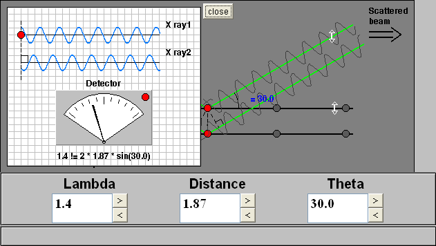
How to Use this Applet
The applet shows two rays incident on two atomic layers of a crystal, e.g., atoms, ions, and molecules, separated by the distance d. The layers look like rows because the layers are projected onto two dimensions and your view is parallel to the layers. The applet begins with the scattered rays in phase and interferring constructively. Bragg's Law is satisfied and diffraction is occurring. The meter indicates how well the phases of the two rays match. The small light on the meter is green when Bragg's equation is satisfied and red when it is not satisfied.
The meter can be observed while the three variables in Bragg's are changed by clicking on the scroll-bar arrows and by typing the values in the boxes. The d and Θ variables can be changed by dragging on the arrows provided on the crystal layers and scattered beam, respectively.
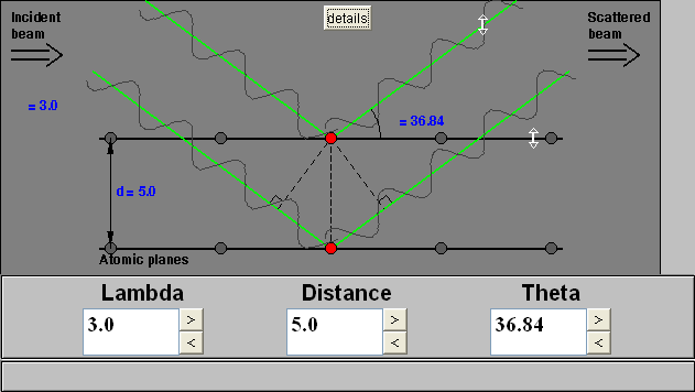
Deriving Bragg's Law
by Paul Schields
Bragg's Law can easily be derived by considering the conditions necessary to make the phases of the beams coincide when the incident angle equals and reflecting angle. The rays of the incident beam are always in phase and parallel up to the point at which the top beam strikes the top layer at atom z (Fig. 1). The second beam continues to the next layer where it is scattered by atom B. The second beam must travel the extra distance AB + BC if the two beams are to continue traveling adjacent and parallel. This extra distance must be an integral (n) multiple of the wavelength (λ) for the phases of the two beams to be the same:
nλ = AB +BC (2).
Fig. 1 Deriving Bragg's Law using the reflection geometry and applying trigonometry. The lower beam must travel the extra distance (AB + BC) to continue traveling parallel and adjacent to the top beam.
Recognizing d as the hypotenuse of the right triangle Abz, we can use trigonometry to relate d and Θ to the distance (AB + BC). The distance AB is opposite Θ so,
AB = d sinΘ(3).
Because AB = BC eq. (2) becomes,
nλ = 2AB (4)
Substituting eq. (3) in eq. (4) we have,
nλ = 2 d sinΘ, (1)
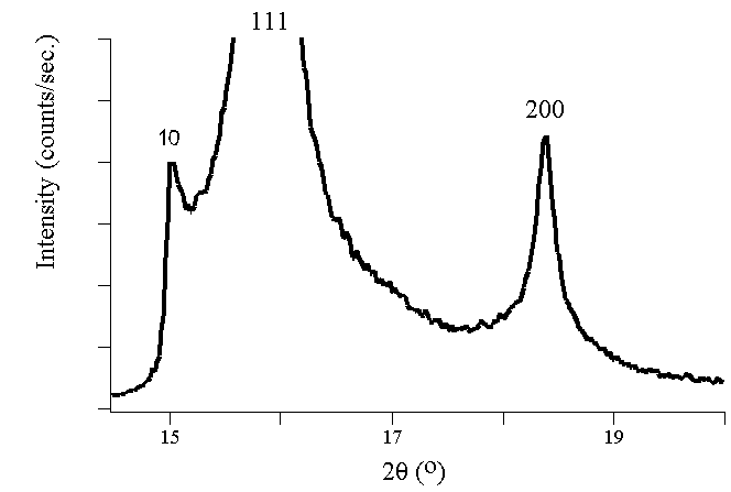
and Bragg's Law has been derived. The location of the surface does not change the derivation of Bragg's Law.Experimental Diffraction Patterns
The following figures show experimental x-ray diffraction patterns of cubic SiC using synchrotron radiation.
Players in the Discovery of X-ray Diffraction
Friedrich and Knipping first observed Roentgenstrahlinterferenzen in 1912 after a hint from their research advisor, Max von Laue, at the University of Munich. Bragg's Law greatly simplified von Laue's description of X-ray interference. The Braggs used crystals in the reflection geometry to analyze the intensity and wavelengths of X-rays (spectra) generated by different materials. Their apparatus for characterizing X-ray spectra was the Bragg spectrometer.
Laue knew that X-rays had wavelengths on the order of 1 Å. After learning that Paul Ewald's optical theories had approximated the distance between atoms in a crystal by the same length, Laue postulated that X-rays would diffract, by analogy to the diffraction of light from small periodic scratches drawn on a solid surface (an optical diffraction grating). In 1918 Ewald constructed a theory, in a form similar to his optical theory, quantitatively explaining the fundamental physical interactions associated with XRD. Elements of Ewald's eloquent theory continue to be useful for many applications in physics.

Do We Have Diamonds?
If we perform a high pressure experiment in a press, such as the Kennedy-Walker split cylinder apparatus, to convert graphite into diamonds, we can use X-ray diffraction techniques to determine whether we achieved the intended result. The carbon atoms in graphite are arranged into planes that are separated by d-spacings of 3.35Å. If we use X-rays with a wavelength (λ) of 1.54Å, and we have diamonds in the material we are testing, we will find peaks on our X-ray pattern at Θ values that correspond to each of the d-spacings that characterize diamond. These d-spacings are 1.075Å, 1.261Å, and 2.06Å. To discover where to expect peaks if diamond, graphite, or both are present, you can set λ to 1.54Å in the applet, and set distance to one of the d-spacings. Then start with Θ at 6 degrees, and vary it until you find a Bragg's condition. Do the same with each of the remaining d-spacings. Remember that in the applet, you are varying Θ, while on the X-ray pattern printout, the angles are given as 2Θ. Consequently, when the applet indicates a Bragg's condition at a particular angle, you must multiply that angle by 2 to locate the angle on the X-ray pattern printout where you would expect a peak.

Determining whether students have met the goals
Teaching materials and tips
- Activity Description/Assignment:
Bragg's Law Activity Sheet (Microsoft Word 35kB Feb24 10)
National Synchrotron Light Source location file for Google Earth (KMZ File 1005bytes Feb19 10)
National Synchrotron Light Source Floor Plan for Google Earth (KMZ File 580kB Feb20 10)
Bragg's Law Applet
Brookhaven National Laboratory
National Synchrotron Light Source - Instructors Notes:
- Solution Set:
Other Materials
Supporting references/URLs
Hyperphysics: Bragg's Law
Wikipedia: Diamond anvil cell
Bragg's Law Applet
High Pressure Laboratory Applet
Wikipedia: Electromagnetic spectrum
Wikipedia: Bragg's Law
Wikipedia: Diffraction
Wikipedia: Bragg diffraction
Wikipedia: Diffraction grating
Wikipedia: X-ray crystallography
NSLS Beamline X17B1
NSLS Beamline X17B2
NSLS Beamline X17B3
NSLS Beamline X17C
