Learning attitude determination and control for satellites using hardware prototype
Summary
This activity allows students to create their own attitude determination and control algorithms on MATLAB and Simulink, and then test them out on Arduino-based physical hardware to determine if their algorithms work in the real world.
Learning Goals
This activity makes use of an Arduino Mega as a microcontroller in order to determine attitude and control the angular motion of an actuator. Students get to understand how attitude determination actually works, how filtering works in context of electronics and how hardware control execution is done. The idea is to provide students with physical hardware where they can test their attitude determination and control algorithm and realize that what works in simulation may not work when implemented on actual hardware. MATLAB and Simulink are used for the coding of the program, which is then uploaded to Arduino. Students need to think about how Simulink blocks come together and work with MATLAB for execution to take place. They need to understand the interface between the hardware and software and how data acquisition and control takes place. It uses critical thinking and model development techniques.
Learning Objectives/Goals
Broadly speaking, this activity has the following learning objectives (optional, "3D printing and CAD" learning objectives are listed in italics, read more about this in "Teaching Notes and Tips"):
A. Cognitive (knowledge & understanding)
- Students will explain the principles of attitude determination and control for satellites (e.g., using sensors like IMU or Inertial Measurement Units, and actuators like stepper motors) as applied in a hardware rig.
- Students will describe how sensor data (from an IMU) is acquired, processed (filtered/fused), and then used to command actuators in a closed‐loop system.
- Students will recognize the practical differences between simulation results and real‐world hardware implementation (e.g., delays, noise, actuator limits).
- Students will understand how 3D printing technology works which can be used for real-world printing of scale models.
B. Skills (application & analysis)
- Students will develop and implement a control algorithm in Simulink/MATLAB that stabilizes a given angular axis (pitch) on the rig.
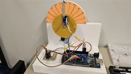
- Students will assemble the hardware rig including the Arduino Mega, IMU (e.g., MPU-6050), stepper motor (28BYJ-48), driver board (ULN2003) and the 3D‐printed structures, following the provided CAD designs.
- Students will test and evaluate their implemented algorithm on the physical hardware, by comparing their prior knowledge of attitude determination and control with the current hardware implementation.
- Students will identify and troubleshoot issues arising in the hardware implementation (sensor calibration errors, mechanical play, motor driver saturation, wiring issues).
- Students will print a 3D model and understand the process of using a digital design to print a real-world object.
C. Affective/Reflective (attitudes & metacognitive)
- Students will reflect on the limitations of purely simulated models and the necessity of physical experimentation in engineering practice.
- Students will demonstrate responsibility for building a safe and functioning experimental setup, including correct wiring, mounting, and handling of electronic/ mechanical components.
- Students will communicate their findings in a concise summary (e.g., a 5‐minute overview) of the design, implementation, and testing of their attitude control rig, including lessons learned.
Context for Use
Students need to be senior undergrads or graduate students to be involved in this activity. An introduction to this activity can be given in a classroom, but students are supposed to work on it themselves and test out their code with the hardware. Two weeks should be given for students to work on this, given the fact that they have the basics of attitude determination, Kalman filtering and controls. The students need to have an intermediate level understanding of MATLAB and Simulink, with some experience with prior coding in the language. Generally, students who are involved in this activity are offered to do this in a group setting, where they produce a report at the end.
To get the students started, a quick demo can be given of how the setup actually works, after which they can think about designing their own code. It can be adapted into other settings with proper planning and ideas if the vision of the activity is clear enough.
Reflection
While the students perform this activity, they should be encouraged to reflect on various parts of this activity to bolster the understanding of what they are actually doing as they go through the motions to complete it. Students can broadly reflect in various stages of this activity as follows:
- Need/motivation for complete this activity and real life applications (refer to the section below for more insights)
- How attitude determination actually works: how acceleration, angular velocity and/or magnetic fields are being detected by an IMU: how does it work at the hardware level (talking about MEMS, Micro‑Electro‑Mechanical Systems can add to that understanding).
- How is data transmission happening between the microcontroller and the PC, and the use of software (MATLAB/Simulink) to achieve the desired goal?
- How is the feedback loop enabling a controlled system.
- Steady state errors and ways to minimize them.
- Hardware accuracy and tolerances
- Other ways: physical hardware, software or experimental setup configurations to achieve the same goals.
Motivation
Students can be inspired/motivated to undertake this project/assignment due to its real life applications:
- AOCS in Satellites: Attitude and orbit control systems, or AOCS is an active area of study and research in the field of Astrodynamics. Satellite AOCS is the set of sensors, actuators, software, and control algorithms that determine and adjust a spacecraft's orientation (attitude). Ensuring that the satellite points the right things in the right directions: antennas to Earth, solar panels to the Sun, payloads to targets is imperative, and this project allows students to get a basic understanding of it.
- Consider talking to students about how the pitch angle obtained using IMU in this project is related to actual attitude determination of a satellite (sensor). And how the stepper motor is related to actual attitude control of a satellite (actuator) and how they work in a feedback loop.
- This problem can be further extended to attitude determination and control problems in drones that use PID control.
Description and Teaching Materials
The instructor needs to download the CAD files and then use a 3D printer to print out the designs. They can choose to offload this to students (to expose them to 3D printing technologies and the process of using digital CAD designs for making physical specimen); see more in the "Teaching Notes and Tips" section. They also need a breadboard, jumper wires, stepper motor, Arduino Mega, MPU6050. This activity was uploaded to GitHub for better visibility. Please click on the link below to access the activity.
Github repo: https://github.com/adarshorbital/satcontrol
![[reuse info]](/images/information_16.png)
Teaching Notes and Tips
Teachers/Instructors/Professors can guide students step by step in working through this activity. Based on the infrastructure available for executing this project, the teaching team can implement this project in the following ways:
- Provide the students with the CAD drawing and hardware needed for the experiment (including 3D printing PLA filament). Henceforth, the student needs to understand how CAD files work, convert them to a .stl file, and then print these designs out using the university 3D printers. This will expose them to the idea of additive manufacturing and can open doors to using 3D printing as a tool for rapid prototyping.
- Provide students with the 3D printed models along with the hardware needed to perform the experiment. The students can directly jump on putting their model and electronics together and then work on executing the Simulink model on their hardware.
Instructors need to decide what approach they would like to use based on the time available for project execution, and the learning outcomes of their course.
Also, note that the current Simulink model works as is, there is no modification needed to make it work. However, the instructor can choose to give students a working model demo (and henceforth ask them to create their own model), or provide just the bare-bones Simulink model (which might not function until the student actually writes the relevant code).
Students should be encouraged to write the code for attitude determination first and then move to the attitude control part of the experiment.
Assessment
Students can be assessed on the fact that how accurately they were able to find the current angle of their IMU (pitch) and how accurately they were able to control the actuator to move it to the appropriate angle. Broadly speaking, they will be assessed on the error between the desired value of pitch angle and the pitch angle obtained during the determination and control activity.
Students need to produce a well-documented code (which will be added as an appendix to the report) and a 5-minute video explaining the entire process of working through this project. Here is a detailed set of rubrics, where 60% of the grade is for technical implementation and 40% of the grade is for communication, reflection, and teamwork.
1. Technical Implementation (60% of grade)
| Criterion | Excellent (A) | Good (B) | Satisfactory (C) | Needs Improvement (D/F) |
|---|---|---|---|---|
| Attitude Determination (Sensor + Filter) | Accurate real-time attitude estimation with well-tuned filter (e.g., complementary/Kalman). Sensor data processed correctly and validated. | Works with minor tuning issues or noise; filter logic mostly correct. | Basic angle estimate achieved but noisy or unstable; filter weak or missing. | Algorithm fails to estimate attitude reliably or produces erratic results. |
| Attitude Control | Control (e.g., PID) achieves fast response, minimal overshoot, stable convergence. Well-tuned and justified. | Control works reasonably with moderate overshoot or slow response. | Control works partially; significant steady-state error or oscillations. | Control fails or unstable; minimal understanding of control principles shown. |
| Hardware Integration & Verification | Full software–hardware integration achieved. System performs as intended with consistent physical response. Clear evidence (data, logs, plots, or video). | Mostly functional; minor wiring or stability issues. | Partial hardware success or intermittent performance. | System not integrated or no successful demonstration. |
| Error Analysis & Performance Metrics | Quantitative analysis (error, settling time, steady-state error) with clear interpretation and sources of error discussed. | Basic metrics reported with limited interpretation. | Some metrics shown but little discussion. | No quantitative performance analysis. |
| Code Quality & Documentation | MATLAB/Simulink code is modular, commented, version-controlled, and clearly explained in README. | Mostly readable and documented. | Functional but disorganized or minimally commented. | Poorly written or undocumented. |
2. Communication, Reflection & Teamwork (40% of the grade)
| Criterion | Excellent (A) | Good (B) | Satisfactory (C) | Needs Improvement (D/F) |
|---|---|---|---|---|
| Project Report / Presentation | Concise, well-structured report (or poster) explaining goals, methods, results, and insights. Includes plots, visuals, and conclusions. | Clear report but with minor missing elements. | Adequate summary with limited visuals or analysis. | Disorganized or incomplete report. |
| 5-Minute Video Explanation | Engaging, clear, and technically sound 5-minute video that explains the system setup, algorithm design, hardware operation, and key results. Demonstrates strong understanding and communication skills. | Clear explanation but minor technical or presentation flaws (timing, clarity, flow). | Understandable but lacks depth, visual clarity, or key details. | Incomplete or unclear video; poor communication or missing demonstration. |
| Reflection on Learning & Challenges | Insightful discussion of lessons learned, troubleshooting steps, and how simulation vs hardware differed. | Reflective but somewhat general. | Mentions challenges superficially. | Minimal or absent reflection. |
| Collaboration & Contribution (Team or Individual) | Teamwork clearly documented; roles defined; even contribution and strong coordination (or for individual, strong initiative and self-management). | Generally good teamwork; small imbalance. | Uneven or loosely coordinated. | Poor communication or minimal contribution. |
| Setup Demonstration & Reproducibility | Setup and operation are clearly shown (photos/videos), wiring and calibration steps documented so others can replicate. | Demonstration present but lacks some details. | Demonstration incomplete or unclear. | No evidence of setup or unclear documentation. |
Note that the 3D printing itself has not been added as part of the rubric here. Since printing a model is simply the matter of having a model printed, you may give a fix amount of the score if they were able to print the model successfully, following appropriate instructions.
References and Resources
1. Arduino Support from MATLABand Simulink: https://www.mathworks.com/hardware-support/arduino.html